Ultimately it is a personal choice, but the tip your iron comes with is a good place to start. While finer points may work better for finer work, fatter tips hold heat better and therefore can be used more quickly and efficiently than finer points. Soldering irons come with many different tips. Do not try to melt the solder and then wipe it where you want it as that will both cause bad joints and get pretty messy. So, how do you solder? The goal is to heat the metal pads and the components and then let them melt the solder. If you look at the front of your PCB, you'll can see the copper traces that are run just under the surface and are exposed in the holes we are going to solder to. This connection is both mechanical (physically holds the parts together) and electrical (allows electricity to flow between them). With a soldering iron we can melt the solder in order to connect two pieces of metal.

For example the melting point of solder is typically about 370F(188C) to 428F(220C) where as the melting point of copper is 1984 F (1085C).

Solder is a specially formulated metal with a relatively low melting point.
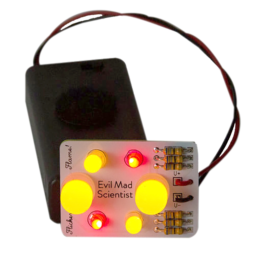
LED FLICKERY FLAME SOLDERING KIT FULL
Here is a picture of the completed board and the full schematic (also found on the back of the PCB). Once you put everything together, our electrons will flow (when the switch is in the On position) and our flashlight will turn on. Flip the switch the other way and the switch physically disconnects those 2 components. A switch is actually a mechanical part, meaning you have to physically move the switch Physically moving the switch will connect the negative pin from your LED to the negative pin of your battery, thus completing the circuit. Using different substances in the diode allow for different colors for our flashlight we chose a white LED. It is a diode that emits light which is very convenient for a flashlight. In this case we are using a light emitting diode, which does exactly what it sounds like. The current can only flow from the positive side (anode) to the negative side (cathode). This is one of the reasons your LED is polarized (meaning it matters which way you hook it up). A diode is 2 pieces of semiconductor placed together to allow current to only flow in one direction. Resistors are not directional, meaning they can be used in the circuit in either a forwards configuration (brown, black, black, gold, brown) or a backwards configuration (brown, gold, black, black, brown) and still function correctly. In this kit we use a 5 band resistor (brown, black, black, gold, brown) this is a 10 Ohm resistor with a 1% tolerance. If you look closely at your resistor you'll notice some color bands.
LED FLICKERY FLAME SOLDERING KIT HOW TO
If you are curious how this works you can check out our LED tutorial to see how to properly size a resistor. This resistor minimizes the current that gets to your LED so we don't give the LED too much current and destroy it. The resistor is like a tube that restricts the amount of current that can get through. Batteries are basically our power house that stores power and outputs that power in terms of current (how fast the electrons are moving) and the voltage (the amount of pressure pushing those electrons through the circuit). Starting with the positive end of the battery, you can see the path it takes along the left side of our PCB up to the resistor. Current is how we measure the flow of those electrons. Consider the battery our source of electrons. This product was added to our catalog on Thursday 22 August, 2013.So, what does our circuit do? A completed circuit is a path where electrons can flow. However, an approximate circuit diagram appears below, but please use the labels on the PCB for component placement.

Please do not ask for instructions as we don't have them, the kits are supplied by a Chinese manufacturer that only supplies Chinese instructions. Note: These kits are supplied without instructions, all the info you need to build it is printed on the PCB. Release the button and the cycle speed steadily decreases until it stops and a random LED remains lit. Press the button and the LEDs start cycling in a circle quite quickly. You will need a fine tipped soldering iron and reasonably good soldering skills to build this kit. Note that this is a new smaller version using primarily SMD components as the older through-hole version of this kit seems to have become unavailable. This simple little kit uses a 555 timer IC to drive a 4017 IC to light one of 10 LEDs in sequence.


 0 kommentar(er)
